
Inspiration
I’ve always been interested in building things to find out how they work, even if it’s something that’s already been done before. My inspiration for this project came when I saw a Hacker News post by Blake Smith showing his adventures in building a USB keyboard.
I was originally thinking of building a full sized keyboard, but I changed my mind after having to enter a load of GUIDs whilst debugging at work. That got me thinking “what if I had a keyboard that could type out a GUID with a single key-press?”. Sure, there are things like AutoHotKey, but where’s the fun in that? No need to pull out the soldering iron… we can change that!
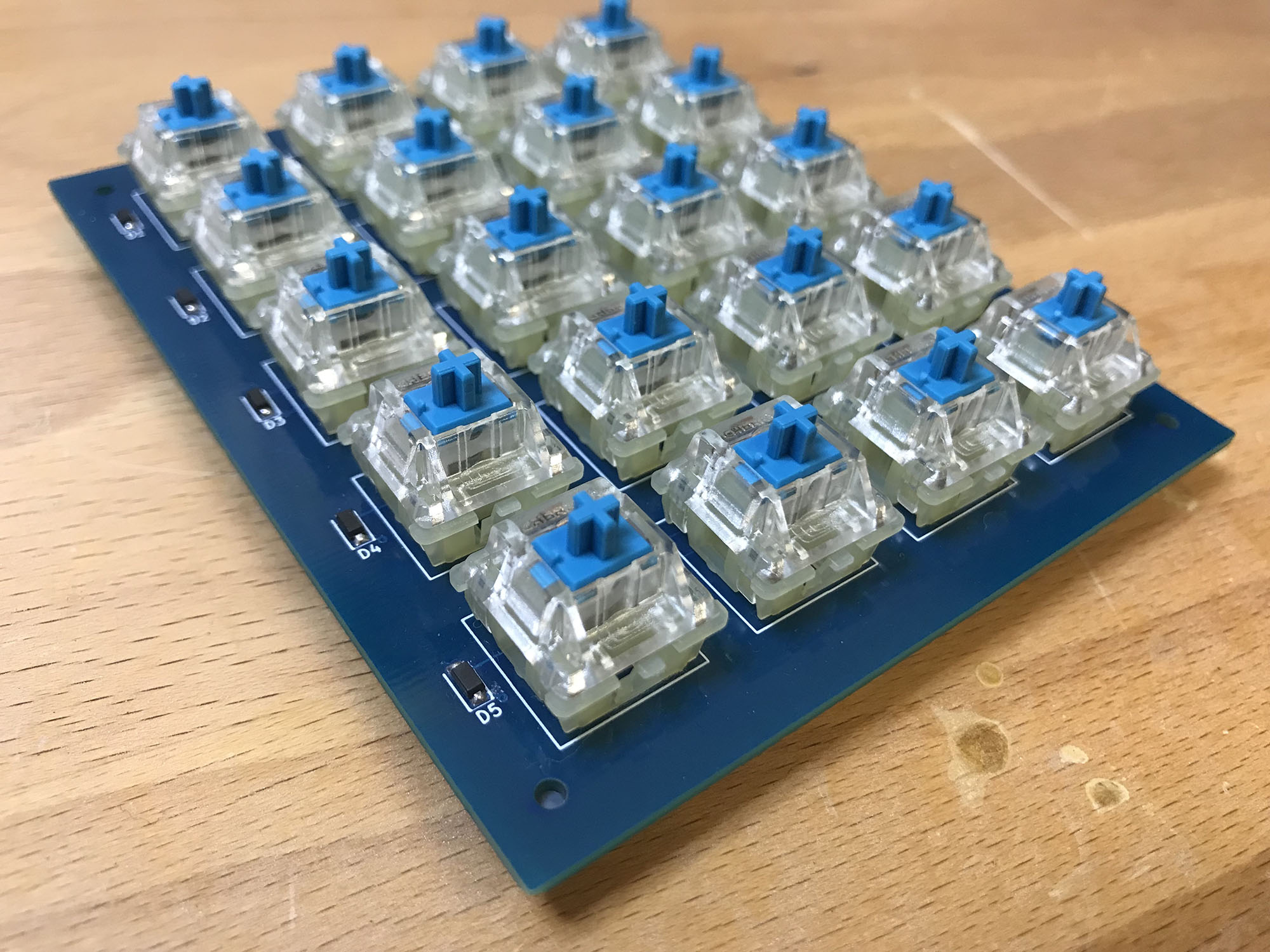
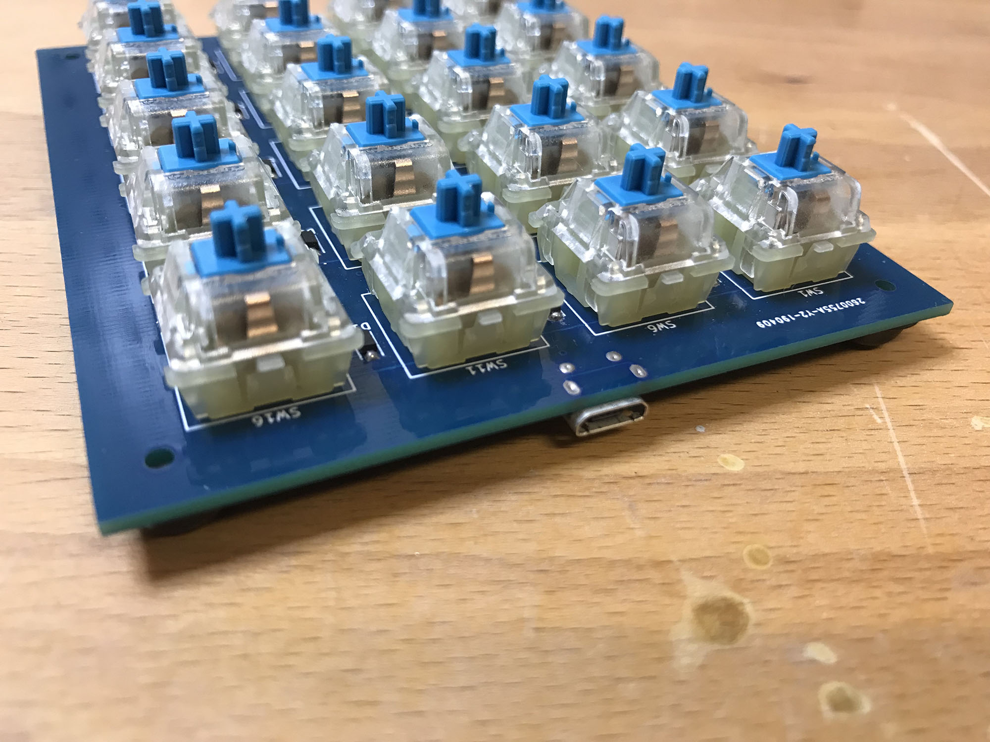
The final keyboard - minus keycaps
I’ve always wanted to learn more about the USB protocol too, so this was a great excuse to get down and dirty with it.
Researching
There is a lot of reference material available online for building your own keyboard, but most of those are just for standard keyboards - it’s hard to find anything about macro keyboards.
Looking around, one of the most popular microcontrollers is the STM32 range by ST Micro - these are ARM 32-bit cores. For this use case, the F0 range would work well, which adheres to the Cortex M0 ARM spec. These are low powered ARM cores - nothing like you would find in your smartphone. I chose to use the STM32F042K6 specifically as it is the highest power chip that can be easily soldered on without using hot air or a reflow oven - plus it supports USB!
I went ahead and ordered the Nucleo STM32F042K6 dev board. Being a huge fan of mechanical keyboards, I went and ordered some Cherry MX keys to play around with too.
Prototyping
Bootstrapping
Once the prototyping parts arrived, I put the Nucleo onto a breadboard. I wanted to understand the full stack of software running on the micro (no wrapper libraries like stm32duino), and I found some great articles and basic sample code covering how to get the STM32F0 up and running on the bare-metal.
A blinking LED, hooray!
Below is the bootstrap assembly code, written in ARM32 assembly. It was adapted from the sample links above, but simplified a little to help me understand what was going on.
.syntax unified
.cpu cortex-m0
.fpu softvfp
.thumb

// Global values.
.global reset_handler


// The reset handler. Called on reset
.type reset_handler, %function
reset_handler:
    // Set the stack pointer to the end of the stack.
    // The '_estack' value is defined in our linker script.
    LDR  r0, =_estack
    MOV  sp, r0

    // Copy data from flash to RAM data init section.
    // R2 will store our progress along the sidata section.
    MOVS r0, #0

    // Load the start/end addresses of the data section,
    // and the start of the data init section.
    LDR  r1, =_sdata
    LDR  r2, =_edata
    LDR  r3, =_sidata
    B copy_sidata_loop

    copy_sidata:
        // Offset the data init section by our copy progress.
        LDR  r4, [r3, r0]
        // Copy the current word into data, and increment.
        STR  r4, [r1, r0]
        ADDS r0, r0, #4

    copy_sidata_loop:
        // Unless we have copied the whole data section, copy the
        // next word from sidata->data.
        ADDS r4, r0, r1
        CMP  r4, r2
        BCC  copy_sidata

    // Once we are done copying the data section into RAM,
    // move on to filling the BSS section with 0s.
    MOVS r0, #0
    LDR  r1, =_sbss
    LDR  r2, =_ebss
    B    reset_bss_loop

    // Zero out the BSS segment.
    reset_bss:
        // Store a 0 and increment by a word.
        STR  r0, [r1]
        ADDS r1, r1, #4

    reset_bss_loop:
        // We will use R1 to count progress here; if we arent
        // done, reset the next word and increment.
        CMP  r1, r2
        BCC  reset_bss

    // Branch to the 'main' method.
    B    main
.size reset_handler, .-reset_handler
This is the actual C program code - shortly we’ll look at how to get rid of the ugly register names and bit shifting magic.
int main ()
{
    // Enable GPIOB peripheral
    RCC->AHBENR |= RCC_AHBENR_GPIOBEN;

    // Setup pin B3 for output and push-pull
    GPIOB->MODER &= ~GPIO_MODER_MODER3;
    GPIOB->MODER |= GPIO_MODER_MODER3_0;
    GPIOB->OTYPER &= ~GPIO_OTYPER_OT_3;

    int counter = 0;
    while (1)
    {
        // Turn on the LED
        GPIOB->BSRR = (1 << 3);
        delay(counter);

        // Turn off the LED
        GPIOB->BRR = (1 << 3);
        delay(counter);

        counter += 10000;
    }
}

void delay(int count) {
    for (int i = 0; i < count; i++) {
        // sleep
    }
}
HAL Integration
The next step was to integrate the bare-metal code with the ST standard library. There is a suite of code known as STM32CubeF0 that you can (and most likely should 😝) use that provides wrappers for most of the low level code for talking over the USB protocol, amongst other functions like I2C, SPI, A2D etc.
Integrating the HAL library was a little annoying… There are quite a few quirks that you can only find out by trawling through the code samples (there was no documentation available for me as I am on OSX and the docs use .chm format 🤦♂️). Also some of the code samples have differences in the way they work - some don’t perform all of the standard initialisation code, so if you want to make use of multiple device features (think USB & I2C), you need to make sure you have got every single line of code from the samples, in the right order too. 👍 Here is a link to the code I ended up with.
Reading button presses and lighting a LED using the HAL
This is the new revised C main program, excluding GPIO and clock setup, see here for the full file. I now had a basic HAL program that can toggle an LED when an external switch is pressed - getting closer…
int main ()
{
    HAL_Init();

    SystemClockConfig();

    SetupGPIO();

    int flashDelay = 0;
    while (1)
    {
        if (flashDelay >= 100000)
        {
            flashDelay = 0;
            HAL_GPIO_TogglePin(GPIOB, GPIO_PIN_3);
        }

        for (int i = 0; i < scanRowsCount; i++)
        {
            if (!HAL_GPIO_ReadPin(scanRows[i].Port, scanRows[i].Pin))
            {
                HAL_GPIO_WritePin(statusLeds[i].Port, statusLeds[i].Pin, GPIO_PIN_SET);
            }
            else
            {
                HAL_GPIO_WritePin(statusLeds[i].Port, statusLeds[i].Pin, GPIO_PIN_RESET);
            }
        }

        flashDelay += 1;
    }
}
USB HID Device
This was probably the most time consuming part of writing the firmware. Getting the USB protocol up and running wasn’t as simple as you may hope. Sure, it may have been harder because I didn’t just copy-paste the code sample, but I feel you shouldn’t have to do that to get it working either.
The first thing that I came across was getting debouncing working on the Cherry MX keys. If you just send the key characters through as the pins get pulled down to ground, you sometimes get multiple key presses.
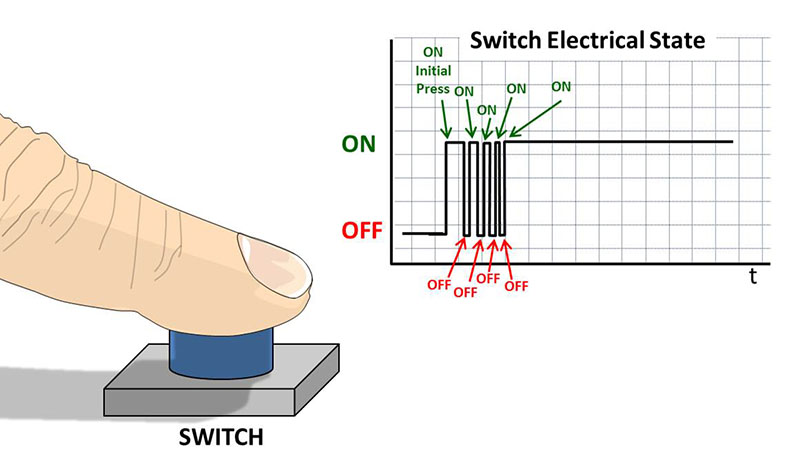
Signal line when pressing a physical switch
Switch debouncing is very common though and has a few different solutions, the one I went for just uses a time delay to wait for the signal to settle.
#define DEBOUNCE_MILLIS 30

for (int i = 0; i < keyCount; i++)
{
    uint8_t pinState = HAL_GPIO_ReadPin(keys[i].Pin.Port, keys[i].Pin.Pin);
    if (pinState != keys[i].State)
    {
        if (millis - keys[i].StateChangeMillis > DEBOUNCE_MILLIS)
        {
            keys[i].State = pinState;
            keys[i].StateChangeMillis = millis;
        }
    }

    //...
}
The next problem was finding out how to send multiple keys in sequence over the USB protocol. The first attempt used all available concurrent keys in the USB HID packet (6 at once), but this had unreliable behaviour - the OS can choose the order those keys get typed out! Sometimes you would get 012345 (correct) and other times you get 523140 (or some other random variation).
HIDKeyboardReport report = {0};

report.Keys[0] = 0x27; // '0' Key
report.Keys[1] = 0x1E; // '1' Key
report.Keys[2] = 0x1F; // '2' Key
report.Keys[3] = 0x20; // '3' Key
report.Keys[4] = 0x21; // '4' Key
report.Keys[5] = 0x22; // '5' Key

// Should type 012345
SendReport(&report);
Luckily I discovered it is easy enough to send macros properly from a keyboard (albeit slower than the above method - thankfully not by much), you just simulate multiple really fast key-presses in sequence - exactly like a barcode reader does!
#define MACRO_KEY_DELAY 20

HIDKeyboardReport report = {0};
uint32_t currentTick = HAL_GetTick();

if (currentTick - lastMacroKeyMillis <= MACRO_KEY_DELAY) {
    return;
}

report.Keys[0] = CharToKeyCode(nextMacroKey);

lastMacroKeyMillis = HAL_GetTick();
This caused another issue which was hard to diagnose - randomly (around 1 in 10) a keypress would not be sent through to the OS, or the OS refused to type it out. This one had me pulling hair out for a few days.
After pulling out Wireshark (yes, you read right, Wireshark! - who knew it could monitor USB?!) I found that multiple packets were getting sent with the same key when this happens… It finally clicked and I worked out that the computer thinks I’m holding the key down. DOH!!! The fix was simple, detect where the same character occurs two in a row and send a blank packet in between - just like a real keyboard ⌨️.
#define MACRO_KEY_DELAY 20

HIDKeyboardReport report = {0};
uint32_t currentTick = HAL_GetTick();

if (currentTick - lastMacroKeyMillis <= MACRO_KEY_DELAY) {
    return;
}

if (nextMacroKeyIsSame)
{
    SendNullReport();
} else {
    report.Keys[0] = CharToKeyCode(nextMacroKey);

    SendReport(&report);
}

lastMacroKeyMillis = HAL_GetTick();
By this stage, I was pretty confident that the firmware could do what I wanted, so I started to design the PCB.
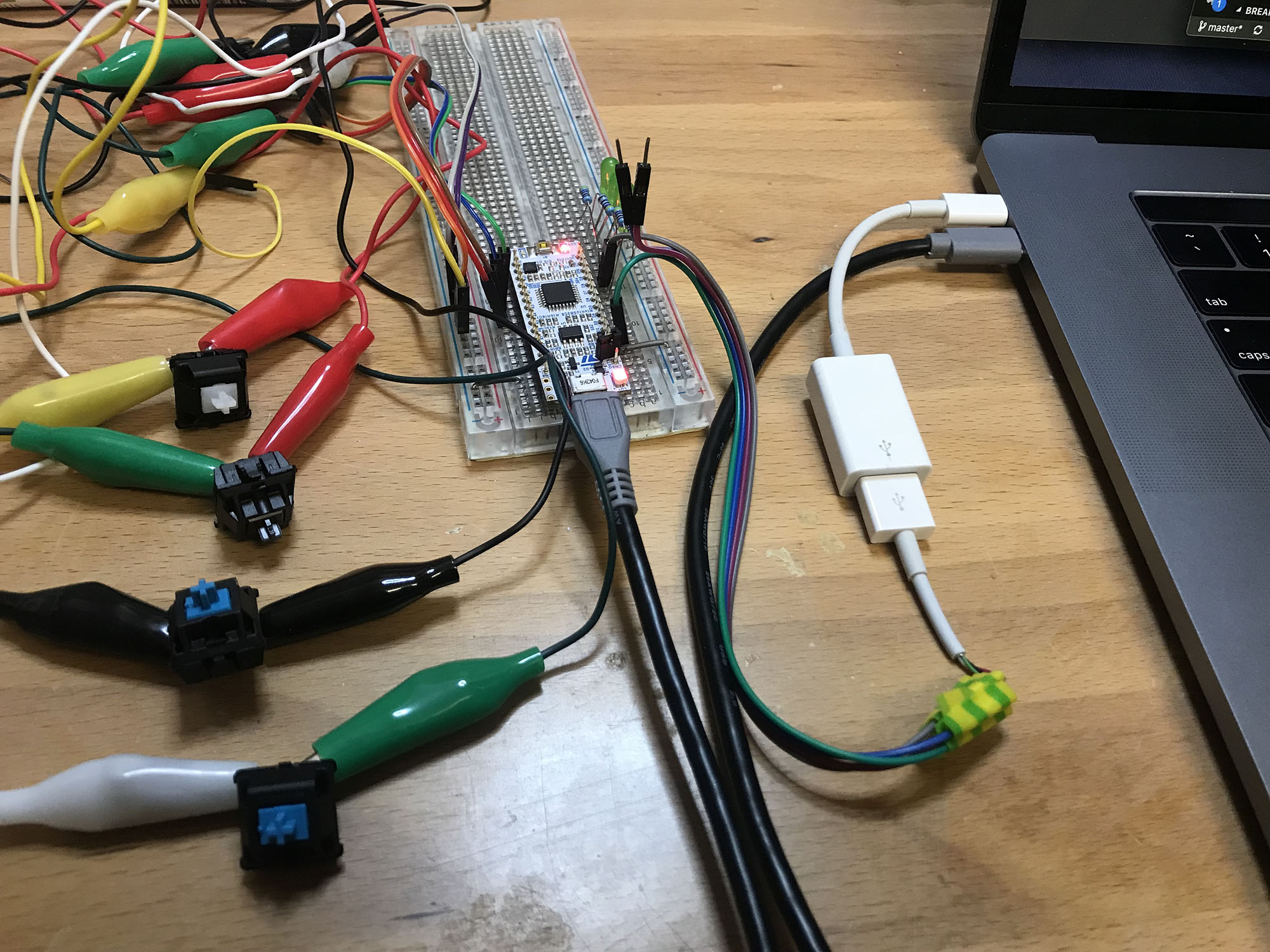
The prototype macro keyboard - complete with a spliced USB connector
PCB Design
Schematics
I started out using Autodesk Eagle, but quickly found out you are limited by board size in the free version (at the time when I was looking) - which wouldn’t work here seeing as the PCB is quite large due to the key layout - around 86mm * 106mm. I switched across to KiCad and found it fairly easy to pickup - there are lots of tutorials and videos out there.
The first step was to create the schematic. I looked at lots of example STM32F0 schematics for reference to find out what filtering capacitors were required and where. The ST reference docs were also quite handy here and listed the requirements out.
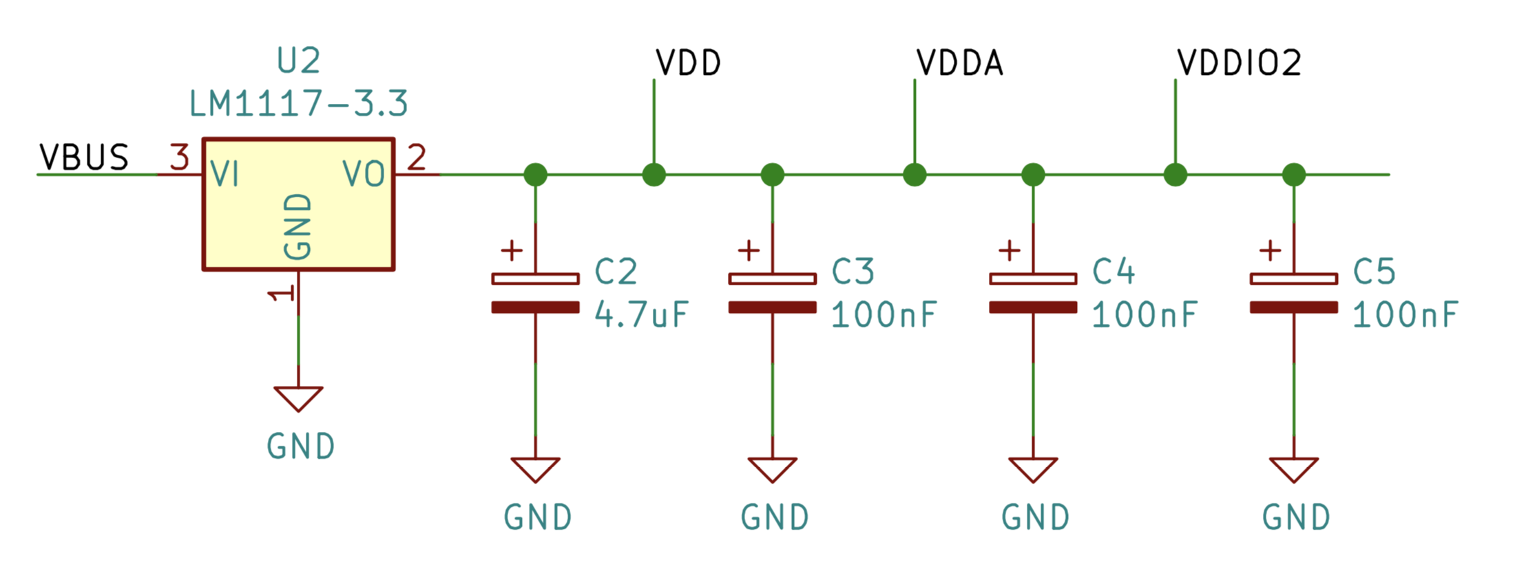
The filtering capacitors placed nearby VDD, VDDA and VDDIO2
Along the way whilst designing the circuit, I found that using a key matrix is important when dealing with any more than 10 keys (depending on your chosen micro) as you quickly run out of GPIO pins. Luckily there are some good guides online that go into detail on how key matrices work.
😴 Tl;dr - you can use a matrix of switches and diodes to reduce the number of pins required for the keys
Number of pins = number of keys across + number of keys high

In my case this was

9 pins = 4 keys across + 5 keys high
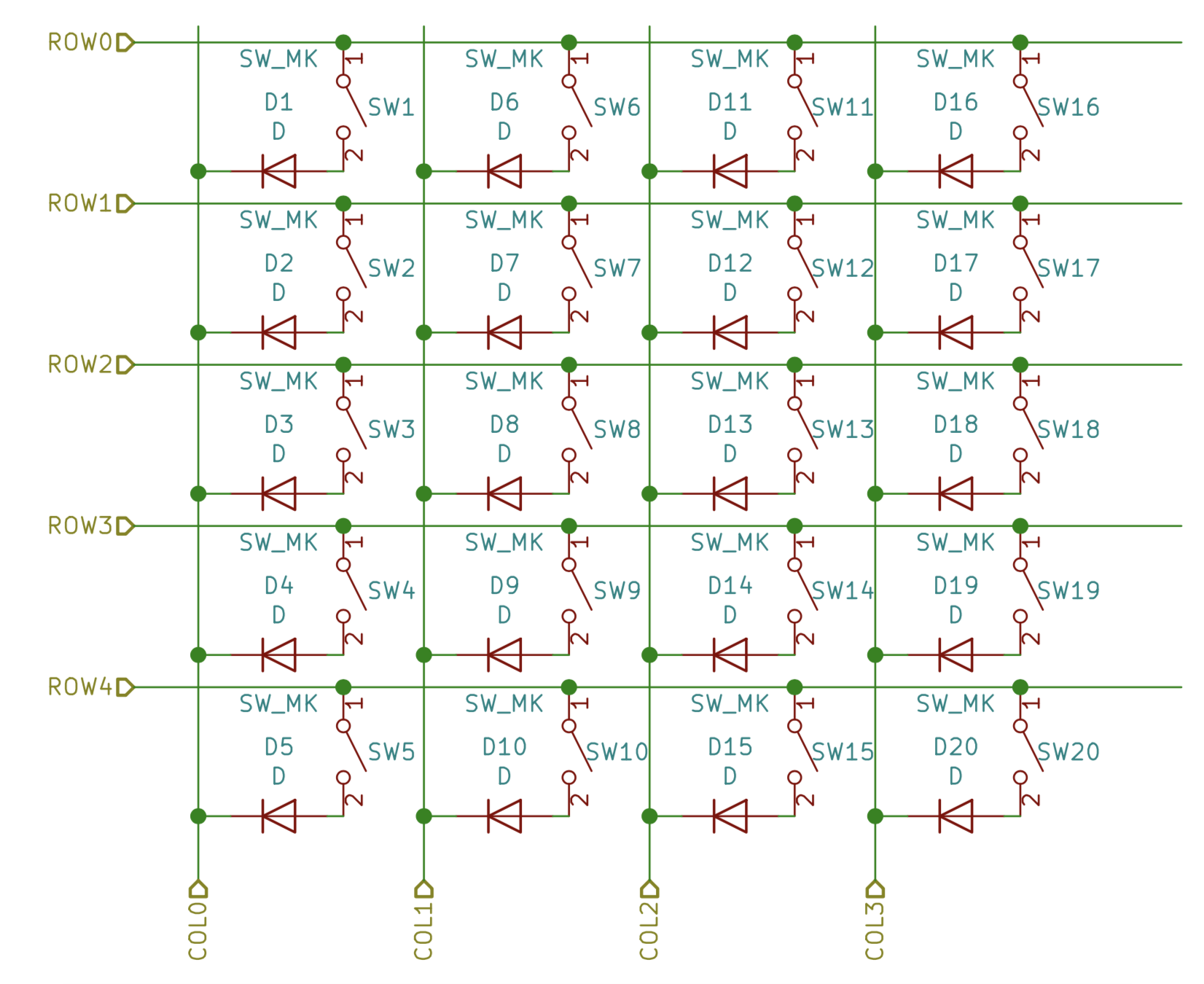
The key matrix for the 4 wide * 5 high keys
I made sure to have an onboard LED for debugging, and a reset switch so I didn’t have to yank the USB every time I wanted to reset.
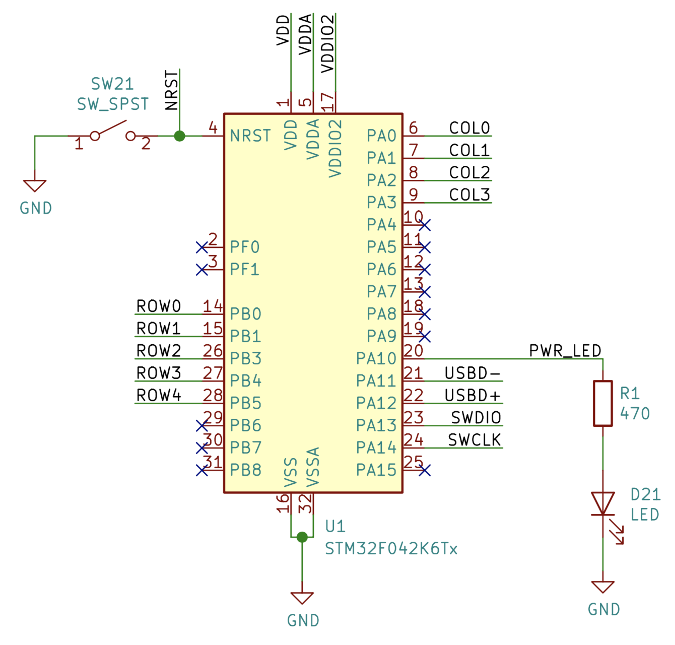
Circuitry around the MCU - reset switch in the top-left, debug LED in the bottom-right
Layout
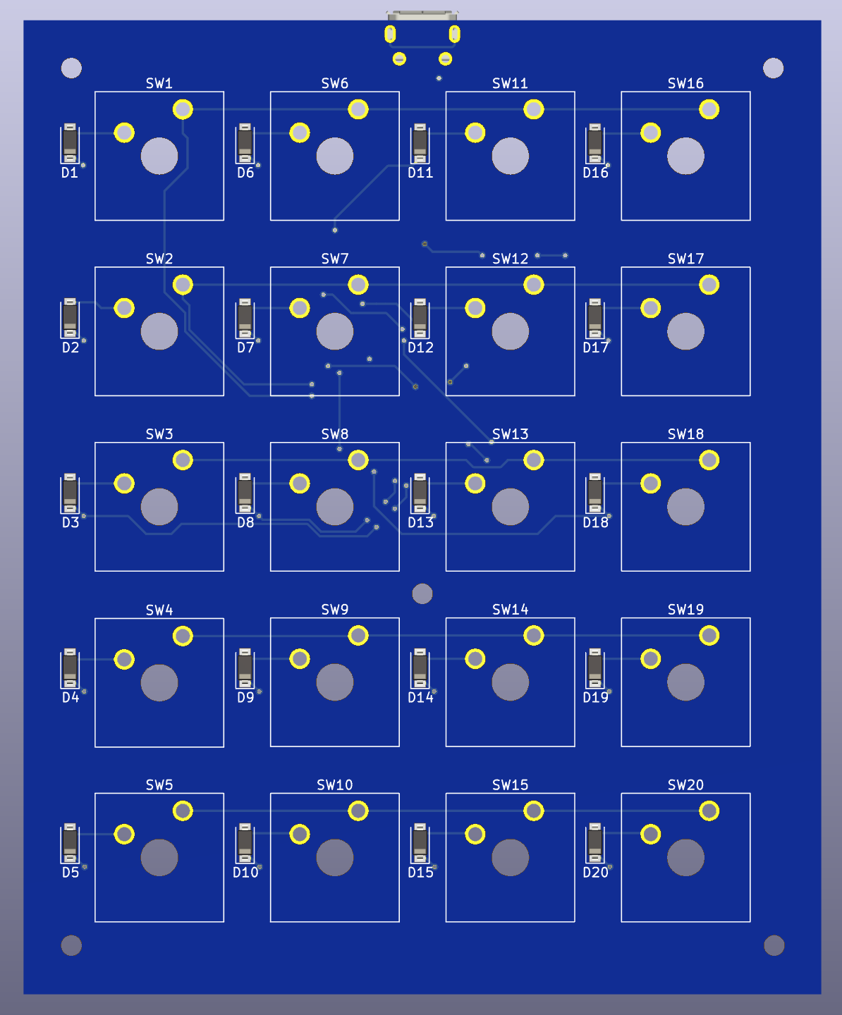
Now that the schematic was complete, it was time to do the layout portion of the PCB. Luckily KiCad has a large library of standard components (including Cherry MX keys 😀 👍) so everything that I needed was already included.
The first step was to place down the keys, as everything else would have to be routed around them. Once this was done, I placed the diodes down on the front side of the panel next to each key. Then I went ahead and placed the USB connector at the top of the board.

The Cherry MX keys laid out with the diodes to the left of each key
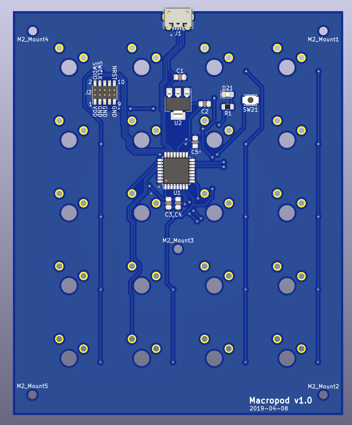
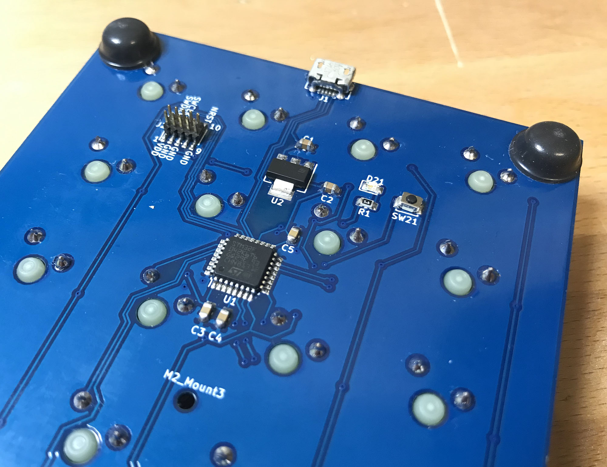
I then chose to place the MCU, voltage regulator and JTAG connector on the back towards the top near the USB connector. Putting the traces down for the MCU ended up being a little tricky towards the end as I was running out of room to nicely route around the outside due to the holes required by the keys - easily solved by sprinkling in some vias.
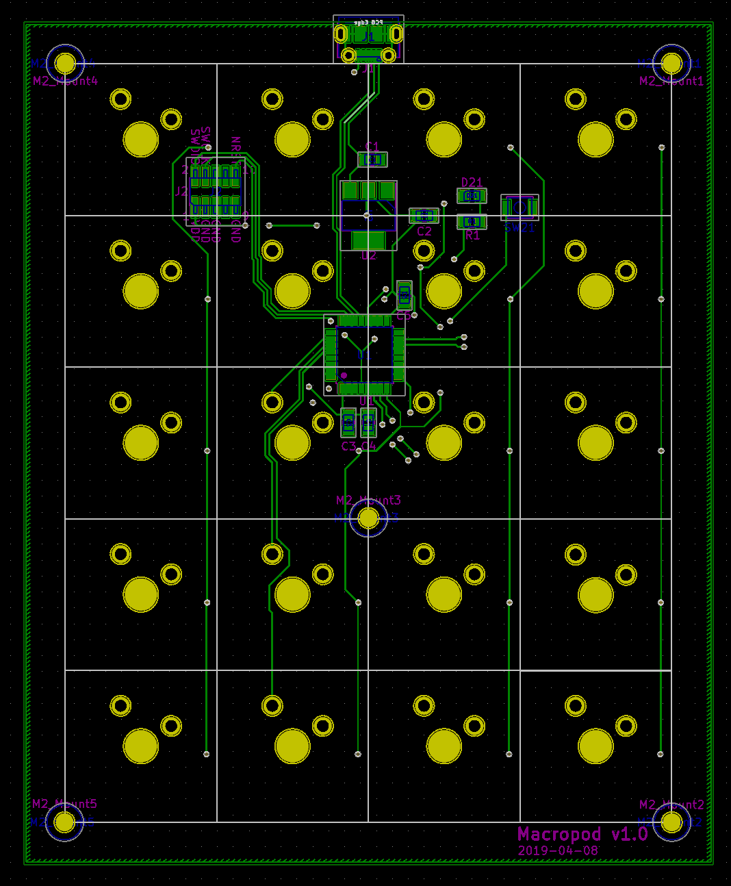
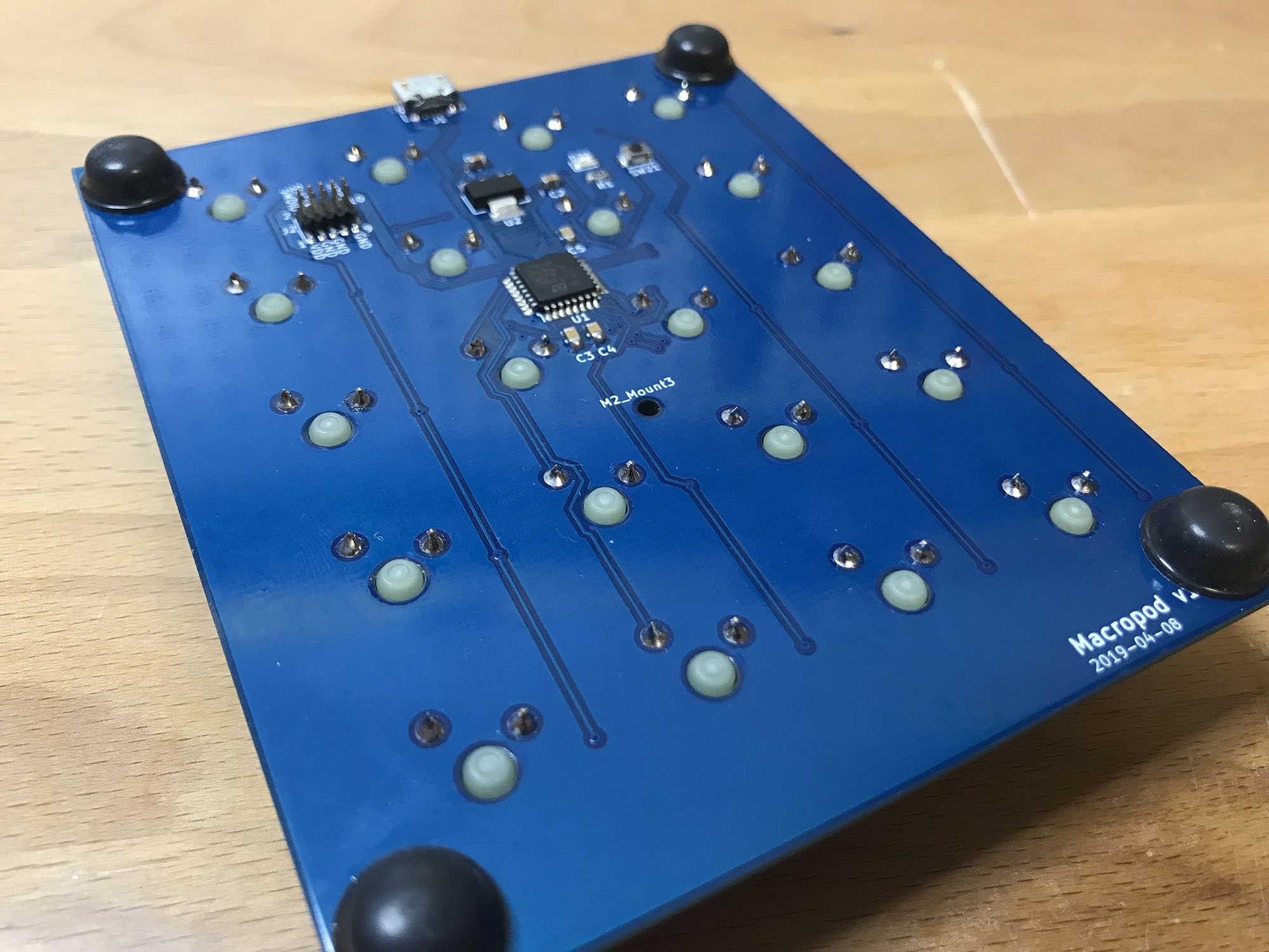
The back of the PCB
The worst mistake I made was not putting the screw holes down until the end, which meant I had to move some of the traces around to fit in nicely. Overall, it was a pretty pain-free process as the PCB scale was quite large and wasn’t very dense with components leaving lots of room to move things around.
The front of the PCB
The back of the PCB
PCB Manufacturing
With the PCB layout complete, it was time to order the PCBs to be built. I chose JLCPCB as I have only heard good things from people using them - they also seem to be very popular among hobbyists and are priced well.
Their ordering process is also fully automated, you can just enter your board parameters and upload you Gerber files, then your board goes into the queue and gets shipped in a day or two. 💯
Ordering Components
I ordered everything from DigiKey, apart from the Cherry MX keys, which I ordered from AliExpress as they were quite a bit cheaper there - plus they have the transparent variant of keys for LED back-lighting (nice to have for future projects 😏).
BOM
Check out the BOM here if you are interested.
Assembly
With all the components in hand, it was time to start assembling.
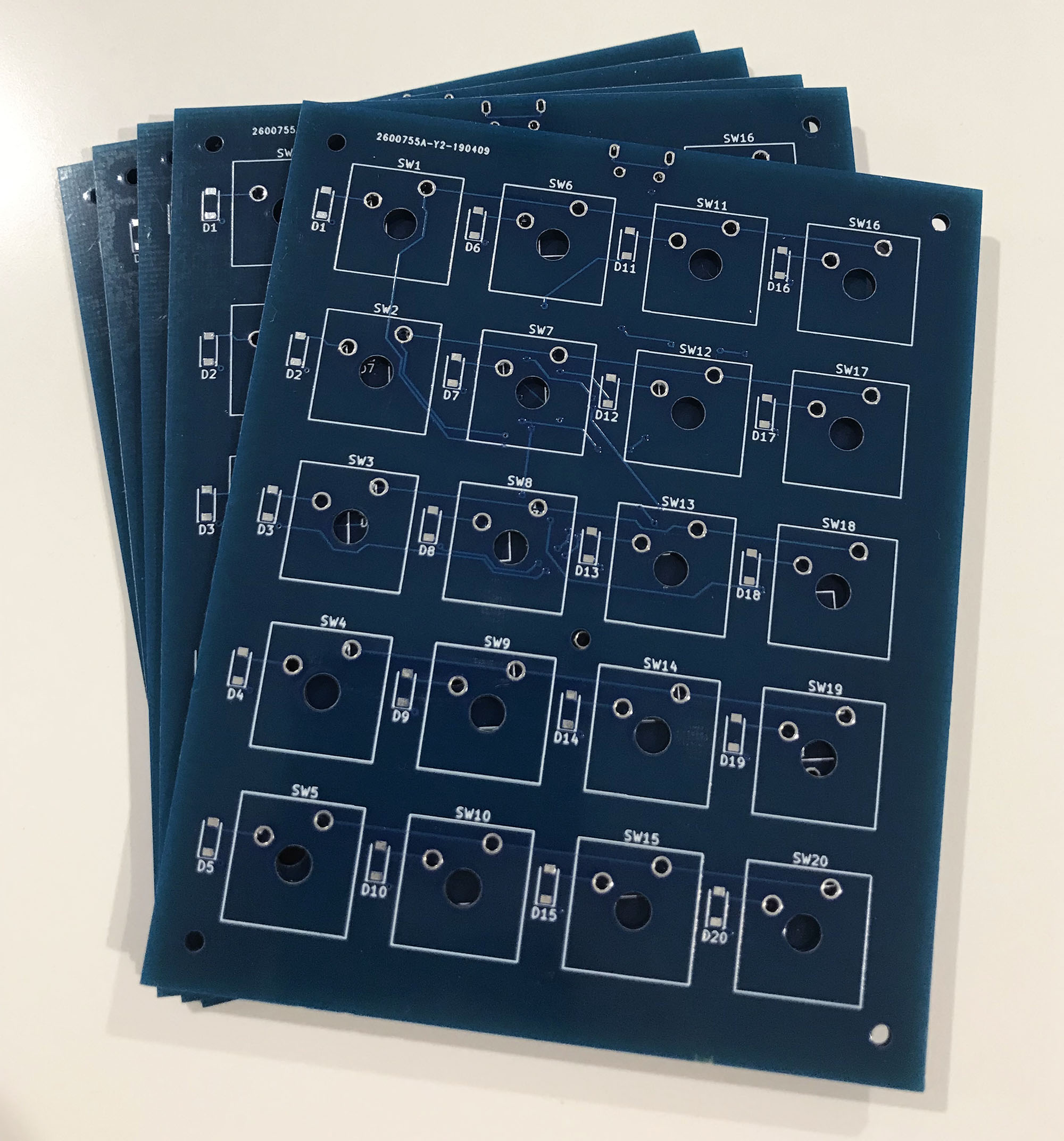
5 fresh PCBs from JLCPCB
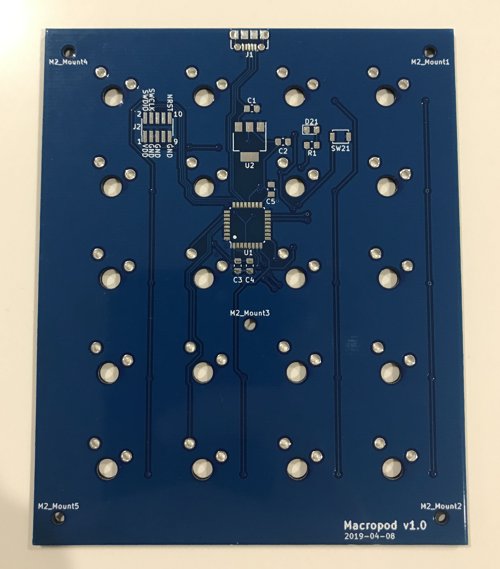
The business side of the PCB
Overall assembly was pretty quick, the longest part was soldering on the 20 diodes and 20 switches, everything else was pretty quick.
I was worried about soldering on the MCU and the JTAG header as they were both surface mount and were more finely pitched than anything I had ever soldered before. I found this drag soldering video which shows a technique using a flux pen and then dragging the soldering iron over the pins. This ended up being super easy and ended up with a result I am pretty happy with. 🍻
Final Firmware
Now the assembly had been completed, it was time for the big test - does the thing work? I hooked the JLink up and hit the flash button and waited in suspense… connecting… it threw an error… $#!% 😡 what was wrong?!
I pulled out the multimeter and started probing around the board. Yep, 3.3V was getting through to the MCU on the power rails so the voltage regulator was doing its job. Hmmm… play around with OpenOCD command arguments… nothing. Flip the JTAG ribbon around… presto! DOH!!!
My firmware loaded up on the board and the LED started blinking! 😮
Now to test out the keys were working… hold on, why did characters just get outputted to the screen? I hadn’t pressed any key… so I started pressing keys, sometimes it works, others it doesn’t. Hmmmm…. maybe the switches are dodgy. I hooked the multimeter up in resistance mode across the switch… 0R when closed and infinite when open… strange, it looks like the switch is behaving like a real switch… no surprise there.
I measured the voltage across the switch lines. The positive side was 3.3V… wait a second, why was the ground side hovering around 1.2V… something isn’t right there. It should be pulled to ground permanently. I started digging around in the code, triple and quadruple checking the GPIO pin initialisations were correct. Everything seemed fine!
After a few days of bashing my head against the wall 🤕 and mulling it over 🤔, I found the issue… a bug 🐛 in the code. It turns out that if you put the GPIO pin initialisation code before you turn on the clock for the GPIO group, the initialisation is ignored. 💥 No errors, no crashes… nothing 👎 Some sort of warning would be nice there!
int main() {
    HAL_Init();

    // Correct place - Liftoff!
    SystemClockConfig();

    SetupGPIO();
    SetupKeyboard();

    // Incorrect place - no bingo
    SystemClockConfig();
}
With this bug out of the way, everything was now working correctly!
End Product
With this being my first foray into custom PCBs and surface mount electronics, I am very happy with the outcome.
Future work
Obviously, no project is ever complete… 😏 so some things I would like to look into in the future are:
- Getting some keycaps to make it a real keyboard
- 3D Printed case - need a 3D printer first 🤞
- Go through more of the DFM process - injection moulding?
- More macro key types (random number generator, key combos like Ctrl+Shift+F)
- USB C connection
- EEPROM for macro storage - perhaps on-the-fly updates?
- LED backlit keys
- Secure encrypted password storage - maybe biometrics for decryption?
As always, if you have any questions or suggestions, I would love to hear from you.